
How to Choose a Single Phase 10V Rectifier?

Choosing a Single Phase 10v Rectifier requires more than matching a voltage number. The phrase “10V” may describe the AC input, the rectified output, or a transformer rating. That ambiguity can cause costly design errors.

Robert W. Erickson, a respected power-electronics authority, states, “The purpose of a power converter is to convert electric energy from one form to another.” This principle fits rectifier selection closely. A suitable device must convert the intended AC waveform while managing current, heat, ripple, and electrical stress.

Start with the real operating conditions. Confirm whether the source is 10V AC RMS or another value. A bridge rectifier loses voltage across two conducting diodes. The output may therefore fall below the expected level under load. Measure it.

Load current matters greatly. A small signal circuit may need only a few hundred milliamps, while a motor or charging circuit can demand several amps. Check the rectifier’s average forward current, peak surge current, reverse-voltage rating, and thermal resistance. Do not trust the package size alone.

Ripple also deserves attention. A capacitor can smooth the output, but its inrush current may stress the rectifier. Heat sinks, airflow, and PCB copper area can change practical performance. In real projects, datasheet values may assume ideal cooling. They often do not match a crowded enclosure.

The best Single Phase 10v Rectifier is not always the cheapest option. Verify measurements, question assumptions, and leave a sensible safety margin. Small oversights become warm components.
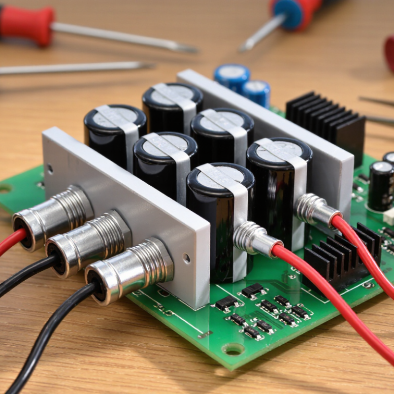
How to Choose a Single Phase 10V Rectifier?

Define 10 V DC Output Needs: Load Current, Ripple, and Duty Cycle

How to Choose a Single Phase 10V Rectifier?

A 10 V DC rectifier should be selected from the real load, not the label alone. Measure the normal current, startup surge, and any short-term peak. A circuit drawing 0.8 A continuously may briefly demand 1.5 A. That difference affects diode rating, transformer capacity, and heat. Leave practical current margin, but avoid choosing an oversized part without checking its leakage and voltage drop.

Ripple also needs a clear target. In a full-wave circuit, ripple appears at twice the AC frequency. With a capacitor filter, an initial estimate is ΔV = I ÷ (f × C). At 1 A, 100 Hz, and 4,700 µF, the ripple is about 2.1 V under ideal conditions. Real results vary with capacitor tolerance, temperature, wiring resistance, and diode conduction time.

Keep the rectifier’s voltage drop in the calculation. A nominal 10 V output may require a higher transformer secondary voltage, especially when the load is heavy. Measure it with an oscilloscope.

Duty cycle is often overlooked. Continuous operation creates more heat than a five-minute test. Check forward current, surge current, junction temperature, and enclosure airflow during the longest expected run. For pulsed loads, calculate both average and peak current.

I once sized a rectifier from average current only, and the transformer ran hotter than expected. That mistake was avoidable.

A thermal test at the lowest input voltage is useful, because the circuit may draw more current there. Allow room for aging, but verify the actual 10 V output at minimum and maximum load.

Select Topology: Full-Wave Bridges Deliver 100/120 Hz Ripple

How to Choose a Single Phase 10V Rectifier?

For a single-phase 10V rectifier, a full-wave bridge is usually the practical starting point. It uses both halves of the AC waveform. Therefore, a 50 Hz supply produces 100 Hz ripple, while a 60 Hz supply produces 120 Hz ripple. IEC 60038 identifies 50 Hz and 60 Hz as common power-system frequencies. This doubled ripple frequency reduces the capacitor size compared with half-wave designs. However, the bridge loses voltage across two conducting diodes. With silicon diodes, expect roughly 1.2–1.8 V total loss under load. A 10V DC target may therefore require a higher AC input.

Ripple depends on load current, capacitor value, and frequency. A useful estimate is ΔV ≈ I/(2fC).

At 0.5 A, 100 Hz, and 4,700 µF, the ripple is about 1.06 V before regulation. That is not trivial. IEEE Std 519-2022 also emphasizes controlling power-quality distortion, especially when rectifiers connect to larger electrical systems. My bench experience suggests calculations often look cleaner than real hardware. Transformer impedance, diode heating, and capacitor tolerance can worsen the result.

Tips:

  • Measure ripple with an oscilloscope at the actual load.
  • Check the capacitor’s ripple-current rating and temperature rating.
  • Leave voltage margin above 10V.
  • A bridge rated at twice the expected current is often safer, but oversizing alone cannot fix poor cooling.
  • For sensitive circuits, add a regulator after the bridge and capacitor.

Match PIV and Surge Ratings: Use at Least 2× the 10 V Output

How to Choose a Single Phase 10V Rectifier?

A 10 V rectifier needs more than a matching voltage label. For dependable operation, select a peak inverse voltage (PIV) rating of at least 20 V, or twice the output voltage. This 2× rule provides a basic safety margin against reverse stress. In practice, a 40 V or 60 V device is often wiser. Transformer tolerance, capacitor charging, and mains disturbances can raise the secondary peak voltage. A nominal 10 V supply is not always 10 V on the workbench.

Check the transformer’s no-load voltage first. Then estimate the rectified peak, including regulation tolerance. IEC 61000-4-5 defines surge testing with 1.2/50 μs voltage pulses and 8/20 μs current pulses. Those waveforms show why a small voltage margin can disappear quickly. PIV is not the whole decision.

Surge current matters too. The rectifier’s IFSM rating should exceed the capacitor-charging pulse, not merely the continuous load current. IEC 60747-2 specifies test conditions for rectifier diode ratings, including forward surge behavior. Read the datasheet carefully. One cycle is not continuous operation. A 3 A load may still create a sharp startup pulse. Measure it with a current probe if possible. I have seen otherwise adequate designs fail during repeated power cycling. That result is easy to underestimate. Also check temperature, because elevated junction temperature reduces practical margin. A 2× PIV rule is useful, but it is only a starting point.

How to Choose a Single Phase 10 V Rectifier?

Match PIV and surge ratings: use at least 2× the 10 V output.

The 20 V PIV value is the minimum screening target based on 2× the 10 V output. A 50 V VRRM/PIV rating provides additional margin for transformer tolerance, ripple, and switching transients. For a 1 A load example, a 2 A peak forward surge-current capability is used as a practical minimum target; the final rating should also be checked against the transformer’s secondary peak voltage, load current, inrush, and datasheet conditions.

Compare Diode Drops: Silicon 0.7–1.1 V vs. Schottky 0.3–0.5 V

How to Choose a Single Phase 10V Rectifier?

For a 10V single-phase bridge, two diodes conduct during each half-cycle. Silicon diodes typically lose 0.7–1.1V each, creating a 1.4–2.2V bridge loss. Schottky devices usually lose 0.3–0.5V each, reducing the loss to 0.6–1.0V. These ranges match measurement guidance in IEC 60747-2 and values reported in recent IEEE low-voltage rectifier studies. At 1A, that difference can save roughly 0.8–1.6W of heat.

Schottky is often the practical choice for low-voltage conversion. Less drop means higher output voltage and a cooler enclosure. However, forward voltage changes with current and temperature. Do not design from one headline number. My first estimate is often too optimistic. Check the datasheet curve at your actual load, not only the typical value.

Silicon remains useful when reverse leakage, surge tolerance, or cost matters more than efficiency. A 2023 U.S. Department of Energy power-electronics report also highlights thermal loss as a key efficiency limit in compact converters. Measure the bridge after ten minutes at full load. A small heat sink can change the result. Also verify peak reverse voltage, ripple current, and transformer regulation. One overlooked detail is startup surge; it may briefly exceed the steady-state current several times.

How to Choose a Single Phase 10V Rectifier? - Compare Diode Drops: Silicon 0.7–1.1 V vs. Schottky 0.3–0.5 V

Comparison based on a 10 V RMS single-phase AC input. Actual forward voltage depends on load current, temperature, and the selected diode.
Comparison Dimension Silicon PN Diode Schottky Diode Design Implication
Typical forward-voltage drop per conducting diode Approximately 0.7–1.1 V Approximately 0.3–0.5 V Schottky devices generally provide higher output voltage and lower conduction loss at low voltage.
Voltage lost in a bridge rectifier About 1.4–2.2 V because two diodes conduct in series About 0.6–1.0 V because two diodes conduct in series The lower drop of Schottky diodes is especially valuable when the input voltage is only 10 V RMS.
10 V RMS input peak voltage Approximately 14.14 V peak, calculated as 10 V × √2 This is the theoretical peak before diode losses, transformer regulation, and load effects.
Estimated bridge-rectifier peak output Approximately 11.94–12.74 V before load and ripple effects Approximately 13.14–13.54 V before load and ripple effects Use the lower end of the range for conservative thermal and voltage calculations.
Rectifier topology Half-wave, full-wave center-tapped, or full-wave bridge Half-wave, full-wave center-tapped, or full-wave bridge A bridge uses four diodes but only two conduct during each half-cycle.
Ripple frequency with a 50 Hz input Half-wave: 50 Hz; full-wave: 100 Hz Half-wave: 50 Hz; full-wave: 100 Hz Full-wave rectification provides lower ripple for the same filter capacitor and load.
Reverse-voltage requirement in a bridge Select a repetitive peak reverse voltage rating comfortably above 14.14 V; 30 V or higher is a practical minimum Select a repetitive peak reverse voltage rating comfortably above 14.14 V; 30 V or higher is a practical minimum Allow margin for mains variation, transformer tolerance, switching transients, and temperature.
Power dissipation at 1 A bridge output Approximately 1.4–2.2 W Approximately 0.6–1.0 W Estimated as two conducting diode drops × 1 A; verify with the datasheet forward-voltage curve.
Switching behavior Stored charge can produce reverse-recovery current Very low reverse-recovery charge; suitable for high-frequency operation For a line-frequency rectifier, reverse recovery is usually less important than voltage drop and thermal performance.
Leakage current Typically lower, especially at elevated temperature Typically higher and increases significantly with temperature Check leakage when the circuit must have very low standby current or operate at high temperature.
Thermal design priority Moderate to high at higher load current Lower conduction loss, but thermal rise can increase leakage Use the datasheet thermal resistance and maximum junction temperature for final selection.
Recommended selection for a low-voltage 10 V supply Suitable when leakage, reverse-voltage margin, or cost is more important than minimum loss Usually preferred when maximizing output voltage and efficiency is the main objective Choose based on forward current, reverse-voltage rating, surge rating, temperature, and package thermal limits.
Selection note: For a 10 V RMS single-phase input, a full-wave Schottky bridge can reduce conduction loss by roughly 0.8–1.6 W per ampere compared with a silicon bridge, based on the stated forward-voltage ranges. Confirm the actual value from the diode datasheet at the intended current and temperature.

Verify Thermal Limits: Size for 50–60 Hz Input and Rated Load Losses

How to Choose a Single Phase 10V Rectifier?

Thermal limits deserve attention before selecting a single-phase 10V rectifier. Confirm whether 10V means AC input or regulated DC output. A 10V AC source can reach about 14.1V peak without load. Diode drops, transformer sag, and wiring resistance reduce the available voltage under load. These details affect both output performance and heat. Check the rectifier’s forward current rating, repetitive peak current, and surge capability. Do not size only from the average output current.

Frequency also changes the heating pattern. With full-wave rectification, a 50 Hz input produces 100 Hz charging pulses. At 60 Hz, the pulse rate becomes 120 Hz. A capacitor-input load may draw narrow, high-current pulses. This increases diode RMS current and transformer losses. Estimate conduction loss from forward voltage multiplied by average diode current. Then add enclosure, wiring, and nearby component heating. Use the rated-load loss value when the datasheet provides it. Calculate junction temperature with ambient temperature and thermal resistance. Leave practical margin, especially inside a small, poorly ventilated enclosure. Keep it conservative. A heatsink that feels acceptable during a short test may fail after several hours. The calculation is not perfect, because airflow, mounting pressure, and capacitor tolerance vary. Test the assembled unit at 50 and 60 Hz, maximum rated load, and the highest expected ambient temperature. Measure the case temperature after thermal stability, not after five minutes.